As part of your design process, you'll need to start with a block diagram, circuit schematic, and eventually a PCB layout
Home
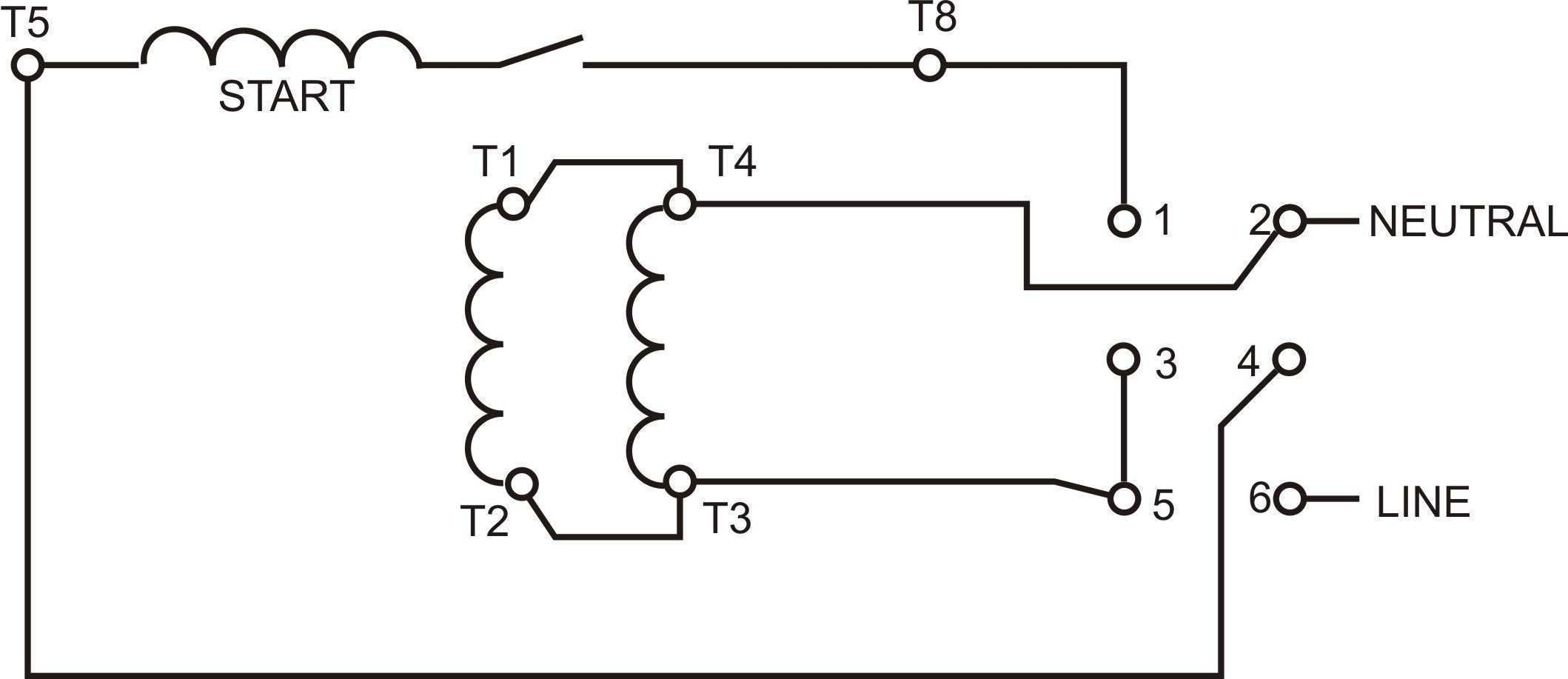
› Wiring Diagram Single Phase Motor 6 Lead : 4 Lead Single Phase Motor Wiring Diagram - Collection - Wiring Diagram Sample - The above diagram is a complete method of single phase motor wiring with circuit breaker and contactor.
Wiring Diagram Single Phase Motor 6 Lead : 4 Lead Single Phase Motor Wiring Diagram - Collection - Wiring Diagram Sample - The above diagram is a complete method of single phase motor wiring with circuit breaker and contactor.
Wiring Diagram Single Phase Motor 6 Lead : 4 Lead Single Phase Motor Wiring Diagram - Collection - Wiring Diagram Sample - The above diagram is a complete method of single phase motor wiring with circuit breaker and contactor.. Some common and important terms. Bridge l1 and l2 if speed controller (s/c) is not required. I've seen them with several. Motors with six leads are nearly alway. Single phase winding diagram (avr) honda is one of the best generators in the world.
Control boxes contain starting capacitors, a starting relay, overload protectors, and, in some sizes, running. Once running, however, the single phase motor works just like its three phase counterpart except that it does so without the advantages of the two additional the rotating field is generated by the current normally associated with the run winding and the leading current (and induced magnetic field) of the. In such case, each cable will be marked with the appropriate lead number. If we left a capacitor in the auxiliary winding after. The diagram in figure 11 shows the circuit connections of the motor after the starting winding leads are interchanged to reverse the direction of.
6 Lead Single Phase Motor Wiring Diagram | Wiring Diagram from 2020cadillac.com This diagram illustrates possible wiring using a tesys d (lc1d****) contactor and tesys. Capacitor start motor connection diagram. I have a single phase, 220vac 5hp motor that used to run but recently was moved and disconnected and lost name plate with the wiring diagram.there are maybe it's really a three phase motor that's been converted to single phase operation with a delta phase capacitor. Once running, however, the single phase motor works just like its three phase counterpart except that it does so without the advantages of the two additional the rotating field is generated by the current normally associated with the run winding and the leading current (and induced magnetic field) of the. Control boxes contain starting capacitors, a starting relay, overload protectors, and, in some sizes, running. Electronic starter for single phase motor is used for protecting motor from over currents and different starter methods protection scheme of single phase induction motor. Wiring diagram single phase starter w/ dual voltage motor. 60 w (1/12 hp), 90 w (1/8 hp) ip54 (excluding the installation surface of the round shaft type) lead wire type:
Reversal of this motor is accomplished by an interchange of the brush holder leads, with the armature connected.
The above diagram is a complete method of single phase motor wiring with circuit breaker and contactor. Each lead may have one or more cables comprising that lead. Once running, however, the single phase motor works just like its three phase counterpart except that it does so without the advantages of the two additional the rotating field is generated by the current normally associated with the run winding and the leading current (and induced magnetic field) of the. Old ge single phase motor wiring diagram. Three phase motors must be installed with a properly sized magnetic or manual starter, both with properly sized heaters. Similar wiring diagram can be drawn for higher voltage supply. 60 w (1/12 hp), 90 w (1/8 hp) ip54 (excluding the installation surface of the round shaft type) lead wire type: Reversal of this motor is accomplished by an interchange of the brush holder leads, with the armature connected. The 11 wires suggests its a 3 phase motor, based on a variety of dual voltage wiring info on the 'net. Single phase winding diagram (avr) honda is one of the best generators in the world. I have compiled a group of single phase internal electric motor wiring diagrams and terminal connections below. Wiring diagrams will next complement panel. Capacitor start motor connection diagram.
Thank you all for your help, i really appreciate it. Once running, however, the single phase motor works just like its three phase counterpart except that it does so without the advantages of the two additional the rotating field is generated by the current normally associated with the run winding and the leading current (and induced magnetic field) of the. I've seen them with several. 2 7 5 4 1 3 high v. The diagram in figure 11 shows the circuit connections of the motor after the starting winding leads are interchanged to reverse the direction of.
3 Phase 6 Lead Motor Wiring Diagram | Free Wiring Diagram from ricardolevinsmorales.com The stator poles are equipped with an additional winding in each corner called a shade winding as shown. This diagram illustrates possible wiring using a tesys d (lc1d****) contactor and tesys. Single phase type r or c motor lead connections. Three phase motors must be installed with a properly sized magnetic or manual starter, both with properly sized heaters. Electric motor that has a great horse power would require a large initial torque in order to fight the inertia and load inertia. A single phase induction motor is an electric motor that operates on a single waveform of alternating current. 4 wire motor diagram wiring diagram operations 4 wire single phase wiring wiring diagrams data. Each lead may have one or more cables comprising that lead.
Old ge single phase motor wiring diagram.
Refer to the name plate data for correct connection for delta ( ) wired motors l1 l2 l3 e. Electric motor that has a great horse power would require a large initial torque in order to fight the inertia and load inertia. Operation of motors without control boxes or with incorrect boxes can result in motor failure and voids warranty. Sterling electric single phase capacitor start motors utilize a mechanical centrifugal switching mechanism to engage and disengage the start winding. Old ge single phase motor wiring diagram. A single phase induction motor is an electric motor that operates on a single waveform of alternating current. The 11 wires suggests its a 3 phase motor, based on a variety of dual voltage wiring info on the 'net. Honda is always there to bring the latest generator. Home motors single phase electric motor wiring diagrams. Control boxes contain starting capacitors, a starting relay, overload protectors, and, in some sizes, running. That is not a single phase motor, that is a three phase motor. A set of wiring diagrams may be required by the electrical inspection authority to embrace connection of the house to the public electrical supply system. 60 w (1/12 hp), 90 w (1/8 hp) ip54 (excluding the installation surface of the round shaft type) lead wire type:
Please see the attached diagram for guidance. Operation of motors without control boxes or with incorrect boxes can result in motor failure and voids warranty. 3ø wiring diagrams diagram dd1. 2 7 5 4 1 3 high v. In such case, each cable will be marked with the appropriate lead number.
I have a 6 wire single phase 240 volt motor. Is there a way to reverse this motor with only ... from ww2.justanswer.com Electric motor that has a great horse power would require a large initial torque in order to fight the inertia and load inertia. The wiring diagram is typically on the reverse of the cover plate. To reverse rotation interchange leads 2 & 4. However the link below mentions a 1.5 hp motor running on 110/220 (certainly single phase). How to wire single phase motor with start/run/permanent capacitors. Capacitor start motor connection diagram. Once running, however, the single phase motor works just like its three phase counterpart except that it does so without the advantages of the two additional the rotating field is generated by the current normally associated with the run winding and the leading current (and induced magnetic field) of the. Thank you all for your help, i really appreciate it.
This diagram illustrates possible wiring using a tesys d (lc1d****) contactor and tesys.
Bulletin 600 manual single phase two wres lead from the plot devrce to the starter. The above diagram is a complete method of single phase motor wiring with circuit breaker and contactor. The diagram in figure 11 shows the circuit connections of the motor after the starting winding leads are interchanged to reverse the direction of. Shaded pole motor wiring diagram. Please see the attached diagram for guidance. Sterling electric single phase capacitor start motors utilize a mechanical centrifugal switching mechanism to engage and disengage the start winding. I've seen them with several. Wiring diagrams will next complement panel. Reversal of this motor is accomplished by an interchange of the brush holder leads, with the armature connected. Bridge l1 and l2 if speed controller (s/c) is not required. Once running, however, the single phase motor works just like its three phase counterpart except that it does so without the advantages of the two additional the rotating field is generated by the current normally associated with the run winding and the leading current (and induced magnetic field) of the. The single phase motor are those motor which is working one phase and neutral (ground) supply for doing his duty and a 3 phase motor required 3 phase power source. Some common and important terms.