As part of your design process, you'll need to start with a block diagram, circuit schematic, and eventually a PCB layout
Home
› Electric Brakes For Trailer Diagram - Wiring Diagram For Tandem Axle Trailer With Brakes / You may be in a position to learn specifically if the tasks should be completed, which makes it easier to suit your needs to properly control your time.
Electric Brakes For Trailer Diagram - Wiring Diagram For Tandem Axle Trailer With Brakes / You may be in a position to learn specifically if the tasks should be completed, which makes it easier to suit your needs to properly control your time.
Electric Brakes For Trailer Diagram - Wiring Diagram For Tandem Axle Trailer With Brakes / You may be in a position to learn specifically if the tasks should be completed, which makes it easier to suit your needs to properly control your time.. Haulmark trailer brake wiring diagram circuit of a cpu for schematics. Click here to shop for electric trailer brakes and brake parts. Route the elecbrakes cable as required, if you internally. If not, the arrangement will not function as it ought to be. Elecbrakes must be connected to trailer wiring circuits as outlined in the wiring diagram.
Blue = electric brakes or hydraulic reverse disable (see blue wire notes below.) in the trailer wiring diagram and connector application chart below, use the first 5 pins, and ignore the rest. When the brake pedal in your tow vehicle is being pressed, the electromagnets in the brakes themselves get activated and your trailer stops. Route the elecbrakes cable as required, if you internally. Trailer wiring diagram electric brakes within brake controller from electric trailer brake wiring with breakaway , source:kanri.info electric so, if you would like obtain all these outstanding pictures related to (electric trailer brake wiring with breakaway ), click on save button to store these pics. Wiring brakes on tandem axle trailer etrailer com how to wire electric a instructions for diagram lights routing wires connectors triple diagrams brake control tech tip page 1 other random car stuff the 24 hours of lemons forums 7 way setup recommendation double land rover defender td5 fuse box schematics source tukune jeanjaures37 fr wiring brakes on tandem… read more »
Diagram Rv Trailer Brake Wiring Diagram Full Version Hd Quality Wiring Diagram Soadiagram Scanomontiferro It from www.etrailer.com The 4 smaller holes represent bolt holes which are used to bolt the backing plate onto the brake flange which sits behind the spindle. Trailer wiring diagram electric brakes within brake controller from electric trailer brake wiring with breakaway , source:kanri.info electric so, if you would like obtain all these outstanding pictures related to (electric trailer brake wiring with breakaway ), click on save button to store these pics. A wiring diagram is a streamlined conventional pictorial representation of an electric circuit. If not, the arrangement will not function as it ought to be. Wiring instructions for electronic brake controls p/n 4399 rev k generic wiring diagram Each component ought to be set and connected with different parts in particular manner. 7 way plug wiring diagram standard wiring* post purpose wire color tm park light green (+) battery feed black rt right turn/brake light brown lt left turn/brake light red s trailer electric brakes blue gd ground white a accessory yellow this is the most common (standard) wiring scheme for rv plugs and the one used by major auto manufacturers today. It reveals the parts of the circuit as streamlined forms, as well as the power and signal connections in between the gadgets.
This automobile is designed not just to travel one location to another but also to carry heavy loads.
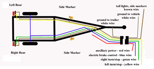
Click on the image to enlarge, and then save it to your computer by right clicking on the image. A wiring diagram is a streamlined conventional pictorial representation of an electric circuit. Trailer wiring connectors various connectors are available from four to seven pins that allow for the transfer of power for the lighting as well as auxiliary functions such as an electric trailer brake controller, backup lights, or a 12v power supply for a winch or interior trailer lights. In addition, wiring diagram provides you with the time frame in which the assignments are to be completed. The following diagram is a general guide for wiring common brake controllers into cars. This automobile is designed not just to travel one location to another but also to carry heavy loads. The two main types of electric brake assemblies for axles 7k and below are forward self adjusting (fsa) and manual adjusting. Dexter nev r adjust 12 25 x 4 electric trailer brake right hand passenger s side 10k lbs axle capacity drum brakes products. The large center circle represents the hole through which the trailer spindle goes, so we can install the backing plate on the axle. The four wires control the turn signals, brake lights and taillights or running lights. White pin to your floor. Assortment of electric trailer brake wiring schematic. If your vehicle is not equipped with a working trailer wiring harness, there are a number of different solutions to provide the perfect fit for.
Click here to shop for electric trailer brakes and brake parts. The service brake circuit must be disconnected from an existing trailer plug. You may be in a position to learn specifically if the tasks should be completed, which makes it easier to suit your needs to properly control your time. Collection of wiring diagram for utility trailer with electric brakes. This 7 pin trailer wiring diagram electric brakes model is more suitable for sophisticated trailers and rvs.
Wiring A Boat Trailer For Brakes And Lights from www.my-inflatable-boat.com Each component ought to be set and connected with different parts in particular manner. Dexter nev r adjust 12 25 x 4 electric trailer brake right hand passenger s side 10k lbs axle capacity drum brakes products. Collection of wiring diagram for utility trailer with electric brakes. Wiring instructions for electronic brake controls p/n 4399 rev k generic wiring diagram In addition, wiring diagram provides you with the time frame in which the assignments are to be completed. A brake controller wiring installation kit makes light work! Trailers with electric brakes need them too. They also provide a wire for a ground connection.
As the name implies, they use four wires to carry out the vital lighting functions.
This automobile is designed not just to travel one location to another but also to carry heavy loads. This 7 pin trailer wiring diagram electric brakes model is more suitable for sophisticated trailers and rvs. Trailer wiring diagrams trailer wiring connectors various connectors are available from four to seven pins that allow for the transfer of power for the lighting as well. Wiring brakes on tandem axle trailer etrailer com how to wire electric a instructions for diagram lights routing wires connectors triple diagrams brake control tech tip page 1 other random car stuff the 24 hours of lemons forums 7 way setup recommendation double land rover defender td5 fuse box schematics source tukune jeanjaures37 fr wiring brakes on tandem… read more » The large center circle represents the hole through which the trailer spindle goes, so we can install the backing plate on the axle. A brake controller wiring installation kit makes light work! You may be in a position to learn specifically if the tasks should be completed, which makes it easier to suit your needs to properly control your time. Blue = electric brakes or hydraulic reverse disable (see blue wire notes below.) in the trailer wiring diagram and connector application chart below, use the first 5 pins, and ignore the rest. A wiring diagram is a streamlined conventional pictorial representation of an electric circuit. Dexter nev r adjust 12 25 x 4 electric trailer brake right hand passenger s side 10k lbs axle capacity drum brakes products. Elecbrakes must be connected to trailer wiring circuits as outlined in the wiring diagram. 7 way plug wiring diagram standard wiring* post purpose wire color tm park light green (+) battery feed black rt right turn/brake light brown lt left turn/brake light red s trailer electric brakes blue gd ground white a accessory yellow this is the most common (standard) wiring scheme for rv plugs and the one used by major auto manufacturers today. Click on the image to enlarge, and then save it to your computer by right clicking on the image.
If your vehicle is not equipped with a working trailer wiring harness, there are a number of different solutions to provide the perfect fit for. Wiring instructions for electronic brake controls p/n 4399 rev k generic wiring diagram Elecbrakes must be connected to trailer wiring circuits as outlined in the wiring diagram. We then run a jumper wire from the electric brake power wire to the right side brake assemblies (see photo). This magnetic action of the brake controller could be checked in the following ways:
The Electric Brake Controller Error Is Still There The Problem Is That Since The Closures The Nearest Gm Dealer Is from ww2.justanswer.com Trailer wiring diagrams trailer wiring connectors various connectors are available from four to seven pins that allow for the transfer of power for the lighting as well as auxiliary functions such as an electric trailer brake controller, backup lights, or a 12v power supply for a winch or interior trailer lights. The basic difference is that your automotive brakes are actuated by hydraulic pressure while your electric trailer brakes are actuated by an electromagnet. In addition, wiring diagram provides you with the time frame in which the assignments are to be completed. Contact technical service for periodic updates. To make wiring a brake controlle Trailer wiring diagram electric brakes within brake controller from electric trailer brake wiring with breakaway , source:kanri.info electric so, if you would like obtain all these outstanding pictures related to (electric trailer brake wiring with breakaway ), click on save button to store these pics. Blue = electric brakes or hydraulic reverse disable (see blue wire notes below.) in the trailer wiring diagram and connector application chart below, use the first 5 pins, and ignore the rest. It reveals the parts of the circuit as streamlined forms, as well as the power and signal connections in between the gadgets.
Collection of wiring diagram for utility trailer with electric brakes.
They also provide a wire for a ground connection. Assortment of electric trailer brake wiring schematic. This magnetic action of the brake controller could be checked in the following ways: Wiring diagram trailer electric brakes valid wiring diagram trailer. When the brake pedal in your tow vehicle is being pressed, the electromagnets in the brakes themselves get activated and your trailer stops. Dexter electric hydraulic disc brake actuator k71 651 00. The four wires control the turn signals, brake lights and taillights or running lights. Click here to shop for electric trailer brakes and brake parts. The controller of a trailer's electrical brake system is a device that feeds the current to your electric brakes. This article will be talking wiring electric trailer brakes diagram.which are the advantages of knowing such knowledge? With all of the brake components connected into the system, the brake will operate as. Electric brakes the electric brakes on your trailer are similar to the drum brakes on your automobile. The 4 smaller holes represent bolt holes which are used to bolt the backing plate onto the brake flange which sits behind the spindle.