As part of your design process, you'll need to start with a block diagram, circuit schematic, and eventually a PCB layout
Home
› Logic Diagram Examples - logical network diagram - DriverLayer Search Engine : A logical dfd focuses on the business and business activities, while a physical dfd looks at how a system is implemented.
Logic Diagram Examples - logical network diagram - DriverLayer Search Engine : A logical dfd focuses on the business and business activities, while a physical dfd looks at how a system is implemented.
Logic Diagram Examples - logical network diagram - DriverLayer Search Engine : A logical dfd focuses on the business and business activities, while a physical dfd looks at how a system is implemented.. The first ladder logic example is from engineer on a disk, which is a marvelous site full of great articles. truth table examples boolean expression simplification logic gate examples here are some logic gate circuit problems: So if both input a and input b are true at the same time, then in the ladder diagram above the first rung is evaluated and output y is set true. Kellogg foundation evaluation handbook (2004) Key components of a logic model • inputs or resources.
Logic gates are the basic building block of digital circuits. The diagram lets the administrators analyze how information flow occurs in different elements like subnets, devices, routers, and other routing systems. Example 1 consider the following circuit gate diagram: We will look at some examples of this now. Network diagrams, both logical and physical, are key to effective network and it infrastructure management.
Logic Gate Circuit Diagram Examples - Wiring Diagram Schemas from www.electronicshub.org Specifically, it is the logic for controlling the steam heat exchanger in the hot water system illustrated below and to the right of it. Here is an example of a logical network diagram, and this depicts how the network connection occurs in this sort of diagram. Include the human, financial, organizational, and community resources available for carrying out a program's activities. The first ladder logic example is from engineer on a disk, which is a marvelous site full of great articles. Network diagrams, both logical and physical, are key to effective network and it infrastructure management. The goal is to determine if the conclusion is valid assuming that the premises are true. A logical dfd focuses on the business and business activities, while a physical dfd looks at how a system is implemented. This network diagram shows how information travels in a network.
Key components of a logic model • inputs or resources.
Example 1 consider the following circuit gate diagram: The logic gate software has all the logic symbols you need to design any kind of logic model. With this easily customizable template, users can represent any existing logical network design. Each gate is a very simple device that only has two states, on and off. And, you will find a number of articles that jay santos wrote and a few that i wrote about control system design and logic diagram development on our magazine articles page. The states of a gate So while any data flow diagram maps out the flow of information for a process or system, the logical diagram provides the what and the physical provides the how. We might want to do this, for example, so that we can investigate simplifying the design. Logical data model diagram procedures. Examples of categorical logic and venn diagrams in each of these examples, two premises and a conclusion will be presented. The logic diagram consists of gates and symbols that can directly replace an expression in boolean arithmetic. Posted by james freeman | 02/27/2021. The goal is to determine if the conclusion is valid assuming that the premises are true.
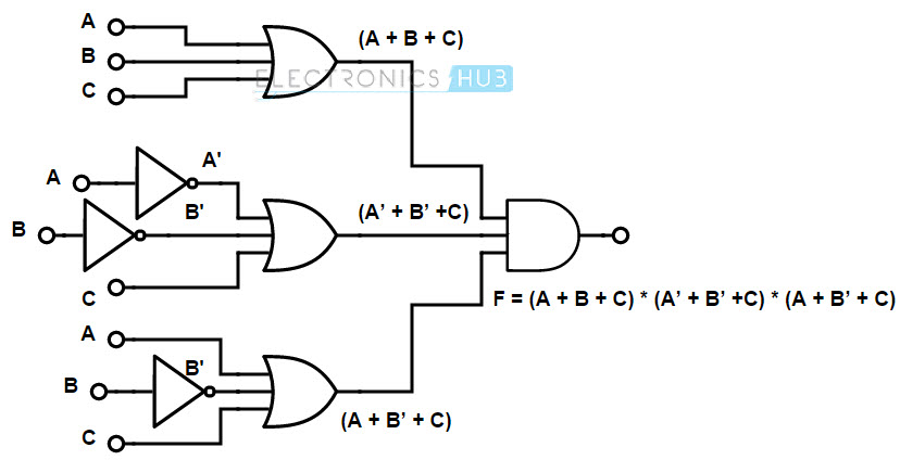
7.2 obtaining boolean expressions from logic diagrams. Example 1 consider the following circuit gate diagram: To do this, evaluate the expression, following proper mathematical order of operations (multiplication before addition, operations inside parentheses before anything else), and draw gates for each step. Each gate is a very simple device that only has two states, on and off. A physical data flow diagram shows how the system will be implemented, including the hardware, software, files, and people in the system.
Example of a Structure and Logic Diagram (Illustrative Example) | Download Scientific Diagram from www.researchgate.net The procedure is best illustrated with the examples that follow. Logic diagrams 3 figure 2 example of figure 1 pump start circuit as a logic diagram. When a logic circuit is given, the boolean expression describing that logic circuit can be obtained by combining the input variables in accordance with the logic gate functions. Here is an example of a logical network diagram, and this depicts how the network connection occurs in this sort of diagram. They are and, or, and not gates. Include the human, financial, organizational, and community resources available for carrying out a program's activities. We will look at some examples of this now. The logic gate software has all the logic symbols you need to design any kind of logic model.
> edraw example > logical network templates and examples.
For inspiration you can look at these good examples of traffic light ladder diagrams: Engineering symbology, prints, & drawings logic diagrams 4 symbology there are three basic types of logic gates. The logic diagram consists of gates and symbols that can directly replace an expression in boolean arithmetic. Network diagrams, both logical and physical, are key to effective network and it infrastructure management. Kellogg foundation evaluation handbook (2004) Logic diagrams 3 figure 2 example of figure 1 pump start circuit as a logic diagram. Logical data model diagram procedures. To do this, evaluate the expression, following proper mathematical order of operations (multiplication before addition, operations inside parentheses before anything else), and draw gates for each step. Great logic model examples can be made quite easily, whether you have references or not. Logic models can be used for different purposes. So if both input a and input b are true at the same time, then in the ladder diagram above the first rung is evaluated and output y is set true. Draw a logic circuit for (a + b)c. Motion process reciprocating a work piece must travel back and forth on a conveyor.
Great logic model examples can be made quite easily, whether you have references or not. By nature it is an abstract visualization, the first step in the design process towards creating a logical and functional database. This logical network sample help users create quality logical network diagrams. Ladder logic diagram symbols wiring diagram schemas logic gates puter science quantum puting diagram circuit diagram boolean expression ab c d 5 input xor gate truth table pictures new idea (a) nuclear zeeman levels scheme and logical labeling for a i = 3 2 download scientific. When a logic circuit is given, the boolean expression describing that logic circuit can be obtained by combining the input variables in accordance with the logic gate functions.
Programming Examples VI | PLC Manual from www.plcmanual.com This network diagram shows how information travels in a network. When logic gates are connected they form a circuit. The goal is to determine if the conclusion is valid assuming that the premises are true. Key components of a logic model • inputs or resources. They are and, or, and not gates. Besides the logic diagram tool, we've put together some logic diagram templates to help. Benefits of logical data flow diagram. For inspiration you can look at these good examples of traffic light ladder diagrams:
To do this, evaluate the expression, following proper mathematical order of operations (multiplication before addition, operations inside parentheses before anything else), and draw gates for each step.
Motion process reciprocating a work piece must travel back and forth on a conveyor. Example 1 consider the following circuit gate diagram: Draw a logic circuit for (a + b)c. No matter you want a logic diagram tool for teaching, or a logic circuit software for engineering purposes, our online logic diagram creator just works perfectly. Kellogg foundation evaluation handbook (2004) Shadows the diagram must not display drop shadows. The goal is to determine if the conclusion is valid assuming that the premises are true. The diagram lets the administrators analyze how information flow occurs in different elements like subnets, devices, routers, and other routing systems. First, all and only the premises will be represented in a single venn diagram. The goal is to determine if the conclusion is valid assuming that the premises are true. Introduction sometimes, we need to be able to derive the boolean expression of a logic gate diagram. Logic models can be used for different purposes. Rung 2 contains one push button (initially on) and one pilot lamp.