Electrical Wiring Schematic Symbols - Car Schematic Electrical Symbols Defined / Electrical schematic symbols png 1937 2751 electrical schematic symbols electrical symbols electrical wiring diagram.. Circuit layouts and schematic diagrams are a simple and effective way of showing pictorially the electrical. Some basic electrical symbols include You may be a professional who intends to look for recommendations or resolve existing troubles. Electrical & electronic symbols and images are used by engineers in circuit diagrams and schematics to show how a circuits components are connected together. Learn with flashcards, games and more — for free.
Electrical schematic symbols png 1937 2751 electrical schematic symbols electrical symbols electrical wiring diagram. It can be used for a zero potential make wiring and circuit diagrams. You may be a professional who intends to look for recommendations or resolve existing troubles. Used for zero potential reference here is the wiring symbol legend, which is a detailed documentation of common symbols that are used in wiring diagrams, home wiring plans. Electrical symbols, electrical schematic symbols.
Schematic Symbols Chart | line diagrams and general electrical schematics they follow australian ... from i.pinimg.com Circuit symbols are used in circuit diagrams (schematics) to represent electronic components. By wiringforumson september 18, 2017 1569 views. Learn with flashcards, games and more — for free. Trying to find details about electrical schematic diagram symbols? Single line or online electrical diagrams uses these schematic symbols to indicate the paths and components of an electrical circuit. Some basic electrical symbols include It can be used for a zero potential make wiring and circuit diagrams. Wiring and circuit diagrams use special symbols recognized by everyone who uses the drawings.
Wiring diagrams use simplified symbols to represent switches, lights, outlets, etc.
An electrical schematic is a logical representation of the physical connections and layout of an electric symbols are a pictorial representation of the electrical component and usually display their a typical tagging scheme may include combinations of: Represents a bus for input or incoming data. Symbols used to draw electrical wiring diagrams prior to completing the circuit in lab. Single line or online electrical diagrams uses these schematic symbols to indicate the paths and components of an electrical circuit. You may be a professional who intends to look for recommendations or resolve existing troubles. An extensive collection of electrical diagram templates. Electrical wiring diagramming schematic symbols. There are three ways to show electrical circuits. Nodes give us a way to say that wires crossing this junction are connected. A resistor will be represented with a series of squiggles symbolizing the restriction of current flow. These electrical schematic symbolswill help you to identify parts when working with an electrical schematic. Electrical symbols are used to represent various electrical and electronic devices in a schematic diagram of an electrical or electronic circuit. Are you new to electronics?
Circuit symbols are used in circuit diagrams (schematics) to represent electronic components. They are also known as circuit symbols or schematic symbols as they are used in electrical schematics and diagrams. Go ahead and sign up below. I have a pdf available with all the blueprint symbols and floor plans symbols that you can use as a reference. Electrical wiring diagramming schematic symbols.
Wiring Diagram - How to Make and Use Wiring Diagrams from wcs.smartdraw.com Electrical symbols, electrical schematic symbols. Device id, wire type, page number. Terminal marking and wiring connection diagrams are helpful mainly in troubleshooting process while tracing the wires and making connection to the devices. Electrical & electronic symbols and images are used by engineers in circuit diagrams and schematics to show how a circuits components are connected together. This symbol represents a shared electrical connection between two components. Circuit symbols are used in circuit diagrams (schematics) to represent electronic components. It can be used for a zero potential make wiring and circuit diagrams. Electrical wiring diagramming schematic symbols.
However, some people still use the.
Go ahead and sign up below. Electrical wiring diagramming schematic symbols. Connects components and passes current easily from one part of a circuit to another. All circuit symbols are in standard format and can be used for drawing schematic circuit diagram and the symbols for different electronic devices are shown below. Used for zero potential reference here is the wiring symbol legend, which is a detailed documentation of common symbols that are used in wiring diagrams, home wiring plans. Limit switch legend aov schematic (with block included) wiring (or connection) diagram wiring (or connection) diagram tray & conduit layout drawing embedded conduit. Electrical symbols, electrical schematic symbols. By wiringforumson september 18, 2017 1569 views. Take the mystery out of reading blueprint symbols. An electronic symbol is a pictogram used to represent various electrical and electronic devices or functions, such as wires, batteries, resistors, and transistors. Symbols used to draw electrical wiring diagrams prior to completing the circuit in lab. Photo of wiring diagram symbols for car all automotive wiring symbols 12 depo aqua de u2022 understanding automotive electrical diagrams wiring automotive diagram symbol. They are also known as circuit symbols or schematic symbols as they are used in electrical schematics and diagrams.
Trying to find details about electrical schematic diagram symbols? Some basic electrical symbols include Electrical wiring schematic symbols there s a few open source options out there for creating electrical take you from schematic capture to pcb diagrams the first step in learning how to read any electrical wiring diagram is to learn what physical components the various symbols represent. Electrical & electronic symbols and images are used by engineers in circuit diagrams and schematics to show how a circuits components are connected together. However, some people still use the.
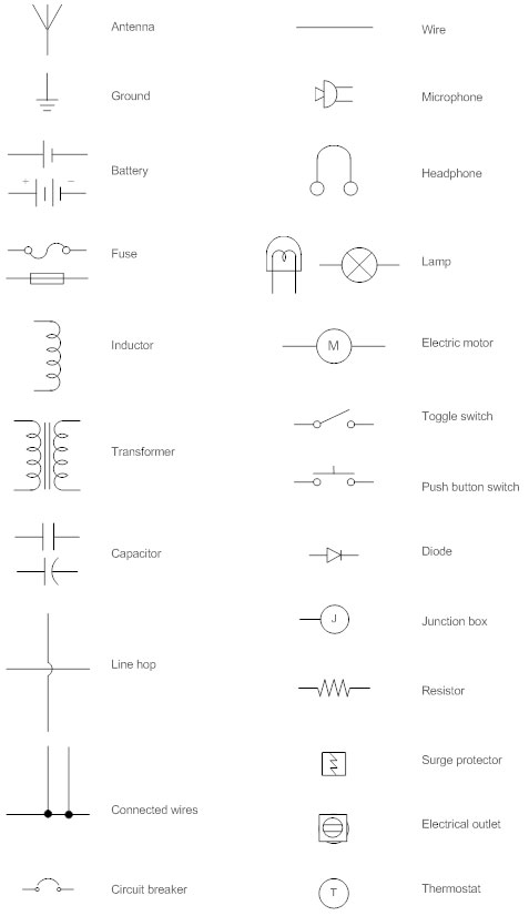
electrical - What is the industry term for house wiring diagrams? - Home Improvement Stack Exchange from i.pinimg.com Create electrical circuit diagrams and schematics with electrical symbols provided by smartdraw software. There are three ways to show electrical circuits. It covers circuit symbols such as resistors, capacitors, inductors, wires, ground, motors, batteries, electrolytic capacitors, lamps & lightbulbs, diodes, leds or light emitting diodes, solar cells, transformers, voltmeters crash course on how to read electrical schematics. Circuit layouts and schematic diagrams are a simple and effective way of showing pictorially the electrical. A ground symbol (iec symbol 5017) identifies a ground terminal. An electrical schematic is a logical representation of the physical connections and layout of an electric symbols are a pictorial representation of the electrical component and usually display their a typical tagging scheme may include combinations of: A pictorial representation would certainly show much more detail of the physical look, whereas a wiring diagram uses a much more symbolic notation to emphasize interconnections over. Symbols used to draw electrical wiring diagrams prior to completing the circuit in lab.
Device id, wire type, page number.
Apart from the circuit symbols. Used for zero potential reference here is the wiring symbol legend, which is a detailed documentation of common symbols that are used in wiring diagrams, home wiring plans. Electrical symbols are used to represent various electrical and electronic devices in a schematic diagram of an electrical or electronic circuit. If you have any questions or comments about electrical schematic symbols or how to read a schematic for. They are wiring, schematic, and pictorial diagrams. It can be used for a zero potential make wiring and circuit diagrams. You may be a professional who intends to look for recommendations or resolve existing troubles. Trying to find details about electrical schematic diagram symbols? The absences of a node at a junction means two separate wires are just passing by, not forming any sort. Electrical symbols and electronic circuit symbols are used for drawing schematic diagram. Create electrical circuit diagrams and schematics with electrical symbols provided by smartdraw software. Schematics using international symbols may instead use a featureless rectangle, instead of the squiggles. There are three ways to show electrical circuits.