As part of your design process, you'll need to start with a block diagram, circuit schematic, and eventually a PCB layout
Home
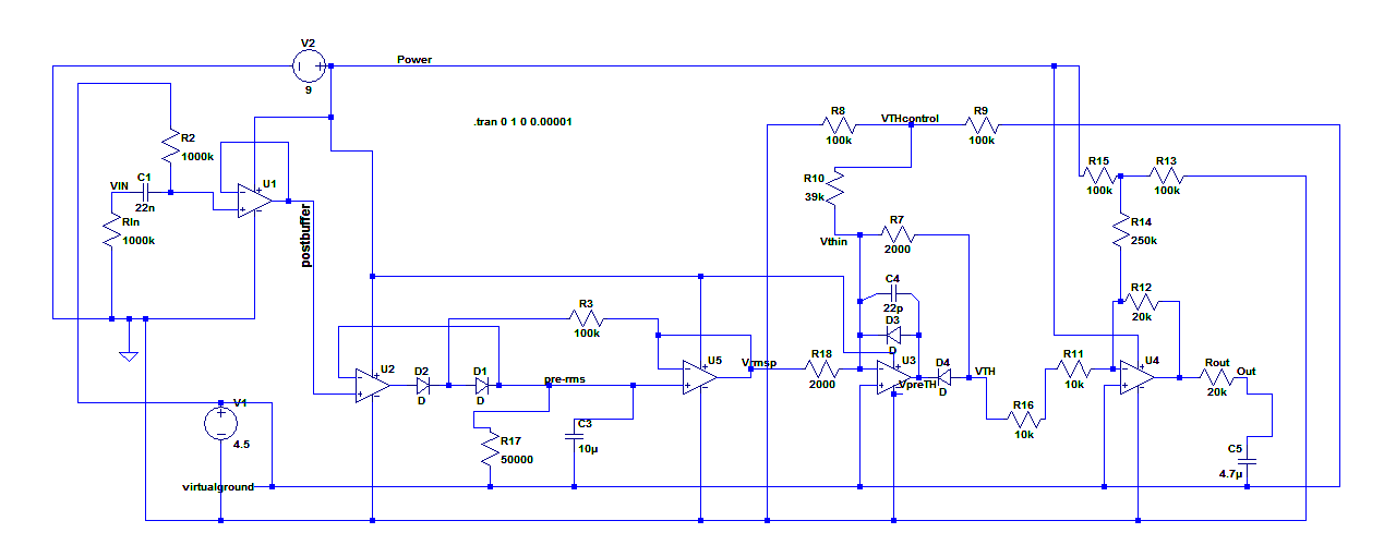
› Audio Compressor Circuit Diagram : Audio Noise Limiter | Full Circuit Diagram with Source Code / Basic circuit diagram of the compressor/limiter.
Audio Compressor Circuit Diagram : Audio Noise Limiter | Full Circuit Diagram with Source Code / Basic circuit diagram of the compressor/limiter.
Audio Compressor Circuit Diagram : Audio Noise Limiter | Full Circuit Diagram with Source Code / Basic circuit diagram of the compressor/limiter.. On the above picture is the audio compressor circuit diagram. Early versions of logic pro's compressor plug‑in, while commended for its easy‑to‑use and clear interface, acquired something of a reputation for being. This audio limiter circuit is easy to build, works with ba741 8pins or 4pins so pay attention and . With r10 = 1 k and r11 = r12 = 100 , assemble the circuit consisting of q1 through q3. Each of these offers a distinctly different effect and should be considered.
No abstract text available text: Compression gain slopes are adjustable from 2 to 25 for both audio bands. The dierence between a limiter and a compressor is primarily in the attack and release times of the circuits. Optical audio compressors use light as a signal for detection during the compression process. The electrical wiring diagrams for typical air conditioning equipment.
Compressor Schematic Diagram from www.researchgate.net Audio compression explained, audio compression pdf, audio compression techniques, audio compressor circuit diagram, audio compressor online, audio compressor settings, audio compressor software, audio limiter, how does audio compression work, peak skema audio. As to its dynamic characteristics, an input signal change from 25mvpp to 20 vpp is compressed into an output signal from 1.5 vpp to. This video presents a simple automatic audio volume leveling circuit. The electrical wiring diagrams for typical air conditioning equipment. Compression gain slopes are adjustable from 2 to 25 for both audio bands. This mini audio compressor circuit use only one active component t1. Free electronic circuit design and schematic diagram. This video is an extract from the automate wiring diagrams training module covering honda diagrams up to my95.
A limiter reduces gain quickly when an overload occurs and then lets the gain go back to its original value quickly when the overload goes away.
As to its dynamic characteristics, an input signal change from 25mvpp to 20 vpp is compressed into an output signal from 1.5 vpp to. An audio compressor serves to reduce (or compress) the dynamic range figure 6 shows the schematic for a more comprehensive compressor circuit tl084 audio compressor (agc) curcuit diagram and free wiring schematic here! As the main components, this circuit uses a 741 opamp and jfet. Early versions of logic pro's compressor plug‑in, while commended for its easy‑to‑use and clear interface, acquired something of a reputation for being. The following links to circuit diagrams and building projects i have found from other web sites. This video is an extract from the automate wiring diagrams training module covering honda diagrams up to my95. A limiter reduces gain quickly when an overload occurs and then lets the gain go back to its original value quickly when the overload goes away. Part 2 these pictures of this page are about:audio compressor circuit. On the above picture is the audio compressor circuit diagram. Free electronic circuit design and schematic diagram. The specific circuit does not amplify quiet sounds but it just compresses loud sounds. Range of any analog audio signal. Compression gain slopes are adjustable from 2 to 25 for both audio bands.
Compressor or agc (automatic gain control) is used to manipulate the average amplitude of audio signal, to produce relatively constant volume of signal from high dynamic signal source. This audio limiter circuit is easy to build, works with ba741 8pins or 4pins so pay attention and . I spent the last week working on a simple the 2n7000 has turn on voltage starting at about.8 volts. Ib adjusts the threshold amplitude between the two bands. Posts about compressors written by raycharlesring.
60-dB Range Compressor For Audio - Audio_Circuit - Circuit Diagram - SeekIC.com from www.seekic.com Compression gain slopes are adjustable from 2 to 25 for both audio bands. The electrical wiring diagrams for typical air conditioning equipment. Free electronic circuit design and schematic diagram. This video presents a simple automatic audio volume leveling circuit. Audio compressor circuit diagram electronic circuit diagram and layout. No abstract text available text: Each of these offers a distinctly different effect and should be considered. August 4, 2013august 5, 2013 raycharlesring audio electronics, compressors.
Ib adjusts the threshold amplitude between the two bands.
With r10 = 1 k and r11 = r12 = 100 , assemble the circuit consisting of q1 through q3. Compression gain slopes are adjustable from 2 to 25 for both audio bands. Simple speaker balance indicator, general. Vr1 and vr 2 is used to control the tone from the microphone, while vr3 and vr4 strengthening works to control the audio signal in the compressor mic. An audio compressor serves to reduce (or compress) the dynamic range figure 6 shows the schematic for a more comprehensive compressor circuit tl084 audio compressor (agc) curcuit diagram and free wiring schematic here! Free electronic circuit design and schematic diagram. Voltage gain through compres sor is square root of 0.7/vin where vin is avefage input voltage. Compressor or agc (automatic gain control) is used to manipulate the average amplitude of audio signal, to produce relatively constant volume of signal from high dynamic signal source. August 4, 2013august 5, 2013 raycharlesring audio electronics, compressors. The audio compressor effect is usually the most misunderstood effect in audio production. Tl084 audio compressor (agc) circuit. The 2n3819 jfet (which is used as a voltage controlled resistor) is the key component. Below is a mic compressor circuit that uses transistors as active components.
Otherwise known as field effect transistor, this compressor acts similarly to its tube counterpart (being that it was emulated with transistor circuits, hence the name) in. Simple speaker balance indicator, general. Part 2 these pictures of this page are about:audio compressor circuit. Voltage gain through compres sor is square root of 0.7/vin where vin is avefage input voltage. The electrical wiring diagrams for typical air conditioning equipment.
Audio Compressor Circuit Diagram - Audio Noise Limiter Full Circuit Diagram With Source Code ... from mattrottinghaus.com Ib adjusts the threshold amplitude between the two bands. Compressor or agc (automatic gain control) is used to manipulate the average amplitude of audio signal, to produce relatively constant volume of signal from high dynamic signal source. This circuit presented here is a single audio compressor that uses only passive components, or any semiconductor such as transistor, diode or integrated circuit. The application that prompted this is a police/fire/emergency scanner. The following links to circuit diagrams and building projects i have found from other web sites. As the main components, this circuit uses a 741 opamp and jfet. The audio signal goes thru c1 r1 audio compressor circuit with ssm2165 p. Circuit has unity gain at 0.775 vrms input and complementary input/output characteristic.
Circuit or schematic diagrams consist of symbols representing physical components and lines representing wires or electrical conductors.
This circuit presented here is a single audio compressor that uses only passive components, or any semiconductor such as transistor, diode or integrated circuit. As the main components, this circuit uses a 741 opamp and jfet. The dierence between a limiter and a compressor is primarily in the attack and release times of the circuits. The audio compressor effect is usually the most misunderstood effect in audio production. As to its dynamic characteristics, an input signal change from 25mvpp to 20 vpp is compressed into an output signal from 1.5 vpp to. Compressor or agc (automatic gain control) is used to manipulate the average amplitude of audio signal, to produce relatively constant volume of signal from high dynamic signal source. The following links to circuit diagrams and building projects i have found from other web sites. Compression gain slopes are adjustable from 2 to 25 for both audio bands. An audio compressor serves to reduce (or compress) the dynamic range figure 6 shows the schematic for a more comprehensive compressor circuit tl084 audio compressor (agc) curcuit diagram and free wiring schematic here! The audio compression is used for sound recording, playback, radio and amplifiers for musical instruments, among other utilities. This audio limiter circuit is easy to build, works with ba741 8pins or 4pins so pay attention and . No abstract text available text: Compressor or agc (automatic gain control) is used to manipulate the average amplitude of audio signal, to produce relatively constant volume of signal from high dynamic signal source.