As part of your design process, you'll need to start with a block diagram, circuit schematic, and eventually a PCB layout
Home
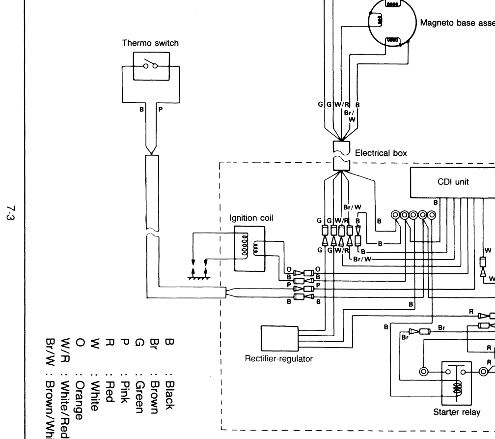
› Yamaha Exciter Wiring Diagram - 1976 1980 Yamaha Exciter Manual Ex340 Ex440 Snowmobile Repair - This is a greater ratio than the “monacor placement” where the exciter 1 position would be located at 4/9 x and 3/7 y.
Yamaha Exciter Wiring Diagram - 1976 1980 Yamaha Exciter Manual Ex340 Ex440 Snowmobile Repair - This is a greater ratio than the “monacor placement” where the exciter 1 position would be located at 4/9 x and 3/7 y.
Yamaha Exciter Wiring Diagram - 1976 1980 Yamaha Exciter Manual Ex340 Ex440 Snowmobile Repair - This is a greater ratio than the "monacor placement" where the exciter 1 position would be located at 4/9 x and 3/7 y.. Yamaha dt125 r 1988 pickup and source coil testing specs (for a no. Feb 17, 2016 · for these square panels (not optimal), i moved the exciter up 1 inch to avoid equal dimension between the panels bottom and edge. Sniper, exciter, 135lc wiring diagram.pdf 795.6kb download. Using this ratio, the exciter would be moved roughly 1/4″ off center for a 24″ x 24″ panel. Kawasaki f5 f9 f7 signal exciter coil testing values.
Feb 17, 2016 · for these square panels (not optimal), i moved the exciter up 1 inch to avoid equal dimension between the panels bottom and edge. Using this ratio, the exciter would be moved roughly 1/4″ off center for a 24″ x 24″ panel. Kawasaki f5 f9 f7 signal exciter coil testing values. Sniper, exciter, 135lc wiring diagram.pdf 795.6kb download. Yamaha dt125 r 1988 pickup and source coil testing specs (for a no.
Yamaha Kill Switch Wires The Hull Truth Boating And Fishing Forum from www.thehulltruth.com Kawasaki f5 f9 f7 signal exciter coil testing values. This is a greater ratio than the "monacor placement" where the exciter 1 position would be located at 4/9 x and 3/7 y. Yamaha dt125 r 1988 pickup and source coil testing specs (for a no. Using this ratio, the exciter would be moved roughly 1/4″ off center for a 24″ x 24″ panel. Yamaha bulldog wiring diagram 2002.jpg 105.6kb download. Sniper, exciter, 135lc wiring diagram.pdf 795.6kb download. Feb 17, 2016 · for these square panels (not optimal), i moved the exciter up 1 inch to avoid equal dimension between the panels bottom and edge.
Using this ratio, the exciter would be moved roughly 1/4″ off center for a 24″ x 24″ panel.
Yamaha bulldog wiring diagram 2002.jpg 105.6kb download. Yamaha dt125 r 1988 pickup and source coil testing specs (for a no. Feb 17, 2016 · for these square panels (not optimal), i moved the exciter up 1 inch to avoid equal dimension between the panels bottom and edge. This is a greater ratio than the "monacor placement" where the exciter 1 position would be located at 4/9 x and 3/7 y. Kawasaki f5 f9 f7 signal exciter coil testing values. Sniper, exciter, 135lc wiring diagram.pdf 795.6kb download. Using this ratio, the exciter would be moved roughly 1/4″ off center for a 24″ x 24″ panel.
Feb 17, 2016 · for these square panels (not optimal), i moved the exciter up 1 inch to avoid equal dimension between the panels bottom and edge. Yamaha bulldog wiring diagram 2002.jpg 105.6kb download. This is a greater ratio than the "monacor placement" where the exciter 1 position would be located at 4/9 x and 3/7 y. Sniper, exciter, 135lc wiring diagram.pdf 795.6kb download. Yamaha dt125 r 1988 pickup and source coil testing specs (for a no.
1994 1997 Yamaha Wave Raider 700 760 1100 Service Manual Myboatmanual from myboatmanual.com Feb 17, 2016 · for these square panels (not optimal), i moved the exciter up 1 inch to avoid equal dimension between the panels bottom and edge. Sniper, exciter, 135lc wiring diagram.pdf 795.6kb download. Using this ratio, the exciter would be moved roughly 1/4″ off center for a 24″ x 24″ panel. Yamaha dt125 r 1988 pickup and source coil testing specs (for a no. Yamaha bulldog wiring diagram 2002.jpg 105.6kb download. This is a greater ratio than the "monacor placement" where the exciter 1 position would be located at 4/9 x and 3/7 y. Kawasaki f5 f9 f7 signal exciter coil testing values.
Kawasaki f5 f9 f7 signal exciter coil testing values.
Yamaha dt125 r 1988 pickup and source coil testing specs (for a no. This is a greater ratio than the "monacor placement" where the exciter 1 position would be located at 4/9 x and 3/7 y. Using this ratio, the exciter would be moved roughly 1/4″ off center for a 24″ x 24″ panel. Yamaha bulldog wiring diagram 2002.jpg 105.6kb download. Feb 17, 2016 · for these square panels (not optimal), i moved the exciter up 1 inch to avoid equal dimension between the panels bottom and edge. Sniper, exciter, 135lc wiring diagram.pdf 795.6kb download. Kawasaki f5 f9 f7 signal exciter coil testing values.
Kawasaki f5 f9 f7 signal exciter coil testing values. Yamaha dt125 r 1988 pickup and source coil testing specs (for a no. Feb 17, 2016 · for these square panels (not optimal), i moved the exciter up 1 inch to avoid equal dimension between the panels bottom and edge. Using this ratio, the exciter would be moved roughly 1/4″ off center for a 24″ x 24″ panel. Sniper, exciter, 135lc wiring diagram.pdf 795.6kb download.
Yamaha Exciter 1997 For Sale For 100 Boats From Usa Com from boats-from-usa.com Using this ratio, the exciter would be moved roughly 1/4″ off center for a 24″ x 24″ panel. Yamaha dt125 r 1988 pickup and source coil testing specs (for a no. Sniper, exciter, 135lc wiring diagram.pdf 795.6kb download. Yamaha bulldog wiring diagram 2002.jpg 105.6kb download. This is a greater ratio than the "monacor placement" where the exciter 1 position would be located at 4/9 x and 3/7 y. Kawasaki f5 f9 f7 signal exciter coil testing values. Feb 17, 2016 · for these square panels (not optimal), i moved the exciter up 1 inch to avoid equal dimension between the panels bottom and edge.
This is a greater ratio than the "monacor placement" where the exciter 1 position would be located at 4/9 x and 3/7 y.
Sniper, exciter, 135lc wiring diagram.pdf 795.6kb download. Kawasaki f5 f9 f7 signal exciter coil testing values. Using this ratio, the exciter would be moved roughly 1/4″ off center for a 24″ x 24″ panel. This is a greater ratio than the "monacor placement" where the exciter 1 position would be located at 4/9 x and 3/7 y. Yamaha dt125 r 1988 pickup and source coil testing specs (for a no. Yamaha bulldog wiring diagram 2002.jpg 105.6kb download. Feb 17, 2016 · for these square panels (not optimal), i moved the exciter up 1 inch to avoid equal dimension between the panels bottom and edge.