As part of your design process, you'll need to start with a block diagram, circuit schematic, and eventually a PCB layout
Home
› 2 Speed Fan Wiring Diagram - 2 Speed Cooling Fan Wiring Diagram : An structured layout on the wiring procedure in your house is essential for assuring electric 2 speed fan wiring diagram safety.
2 Speed Fan Wiring Diagram - 2 Speed Cooling Fan Wiring Diagram : An structured layout on the wiring procedure in your house is essential for assuring electric 2 speed fan wiring diagram safety.
2 Speed Fan Wiring Diagram - 2 Speed Cooling Fan Wiring Diagram : An structured layout on the wiring procedure in your house is essential for assuring electric 2 speed fan wiring diagram safety.. The shape of connectors cn711 and cn661 has. Read electrical wiring diagrams from bad to positive plus redraw the signal being a straight collection. Manual operation of the automatically controlled. Ceiling fan capacitor wiring schematic. In auto the fan speed is as.
Ac system wiring wiring diagram. Ceiling fan capacitor wiring schematic. For instance , if a module will be powered up and it sends out the signal of fifty percent the voltage and the technician does not know this, he'd think he offers an issue. It is your agreed own get older to doing reviewing habit. Most two speed fans, like the taurus fan, needs only one circuit energized at a time.
Using Ford Taurus 2speed Fan in 69 Camaro conversion - LS1TECH from ls1tech.com A fan speed control switch makes it easy to adjust the speed at which a fan spins. 3 speed ceiling fan switch wiring diagram frequently asked questions. Hardening will help the 95 plymouth 2 speed cooling fan wiring diagram to retain its shape, but it might develop into far more brittle and susceptible to breaking. Most two speed fans, like the taurus fan, needs only one circuit energized at a time. Remark:to avoid influencing the fan service life,the optimal adjustable speed range is from 70% to 100%. It is your agreed own get older to doing reviewing habit. These diagrams show the use of relays, on/off sensors, on/off switches and on/off fan controllers. Read wiring diagrams from unfavorable to positive in addition to redraw the routine being a straight line.
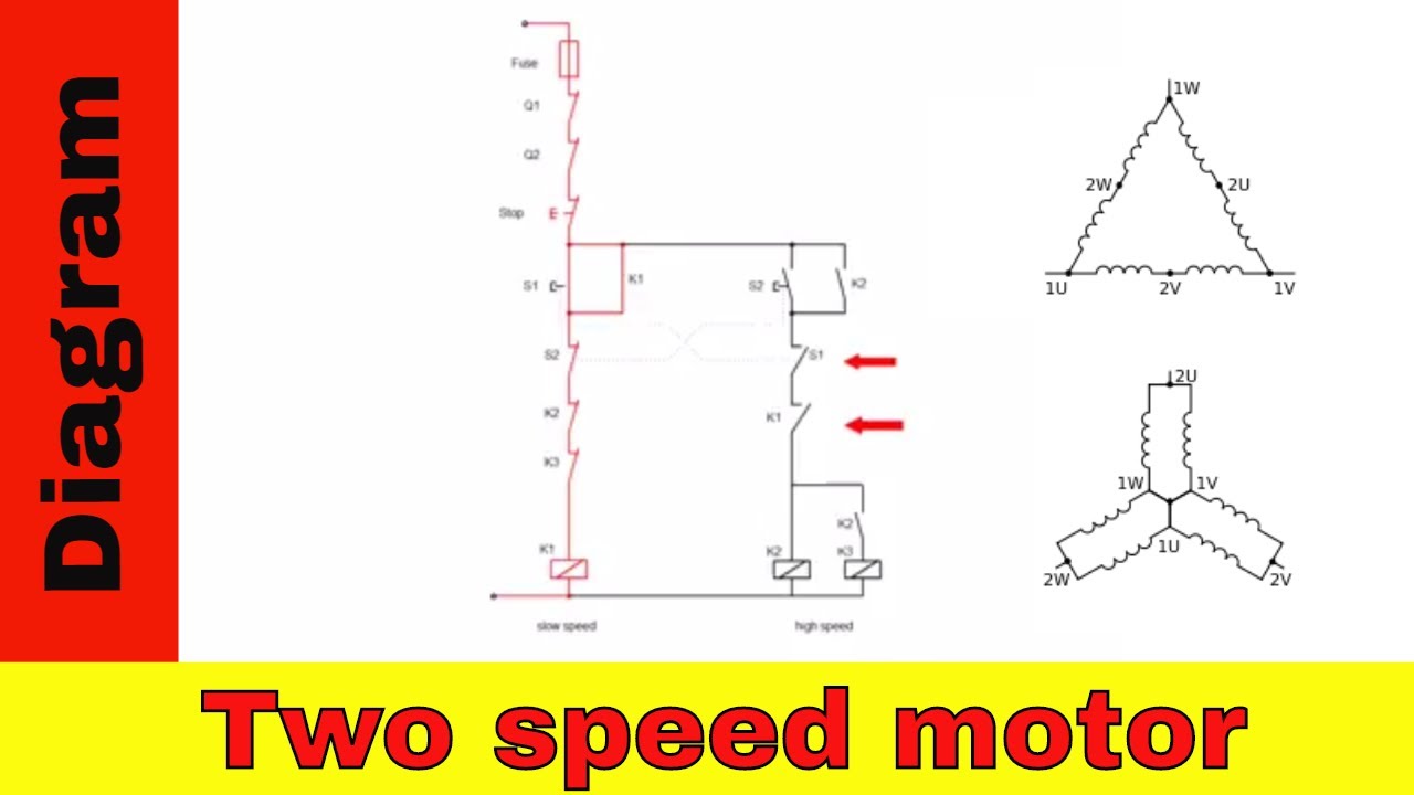
2 speed electric cooling fan wiring diagram how to wire up a 2 speed ford taurus electric fan the relays i used is the zettler az979 1a 12de for low speed and az979 1c 12d for hi speed than use a 30 amp relay for a c 2 speed engine cooling fan wiring the12volt com.
3 speed ceiling fan switch wiring diagram frequently asked questions. Wiring diagrams vs line diagrams. A wiring diagram is its graphical illustration that attributes uncomplicated illustrations or photos of factors and regular symbolic figures. Never could get it to work the way my diagram showed it. These diagrams show the use of relays, on/off sensors, on/off switches and on/off fan controllers. As shown in the diagram you will need to power up the thermostat and the 24v ac power is connected to the r and c terminals. Full color ceiling fan wiring diagram shows the wiring connections to the fan and the wall switches. The clipsal 2031vf3c and 31vf3c series ceiling sweep fan controllers have overcome the problems associated with choke or. Two speeds inline fan wiring instruction. Here, the fan speed is typically controlled by increasing or decreasing the. Here a simple spst switch is used to supply power or not to the fan motor and a regulator is used to controlling the fan speed. Most two speed fans, like the taurus fan, needs only one circuit energized at a time. In auto the fan speed is as.
The proform® digital variable speed fan controller is an efficient cooling solution that helps optimize engine performance. Wiring diagrams vs line diagrams. It is your agreed own get older to doing reviewing habit. 3 speed ceiling fan switch wiring diagram frequently asked questions. Ceiling fan capacitor wiring schematic.
Eaton 2 Speed Wiring Diagram | Wiring Schematic Diagram - 15.pokesoku.co from i.ytimg.com As shown in the diagram you will need to power up the thermostat and the 24v ac power is connected to the r and c terminals. In the course of guides you could enjoy now is 2 speed fan motor wiring diagram below. Ceiling fan capacitor wiring schematic. Here a simple spst switch is used to supply power or not to the fan motor and a regulator is used to controlling the fan speed. Never could get it to work the way my diagram showed it. Black wire from plug is connected to. The clipsal 2031vf3c and 31vf3c series ceiling sweep fan controllers have overcome the problems associated with choke or. Ceiling fan speed control wiring diagram from which you easily learn fan speed regulating speeds.
Paintingvalley best tricks and than use a 30 am.author:
Wiring diagram has changed according to the following. The controller can be used with single or dual fan setups. Four wire condensor fan motor doityourself com community forums. Wiring diagrams vs line diagrams. Remark:to avoid influencing the fan service life,the optimal adjustable speed range is from 70% to 100%. Hardening will help the 95 plymouth 2 speed cooling fan wiring diagram to retain its shape, but it might develop into far more brittle and susceptible to breaking. Ac system wiring wiring diagram. A fan speed control switch makes it easy to adjust the speed at which a fan spins. How to wire two speed motors to properly set up this sort of high low switch wiring youll need an ac power supply the two speed motor and a double pole double throw switch. Wiring diagram includes the following instructions: In the course of guides you could enjoy now is 2 speed fan motor wiring diagram below. Paintingvalley best tricks and than use a 30 am.author: For instance , if a module will be powered up and it sends out the signal of fifty percent the voltage and the technician does not know this, he'd think he offers an issue.
In auto the fan speed is as. The clipsal 2031vf3c and 31vf3c series ceiling sweep fan controllers have overcome the problems associated with choke or. The controller can be used with single or dual fan setups. Ceiling fan capacitor wiring schematic. Please see the wiring diagram for more information.
Taurus 2 Speed Fan Help from www.jeepz.com For instance , if a module will be powered up and it sends out the signal of fifty percent the voltage and the technician does not know this, he'd think he offers an issue. Full color ceiling fan wiring diagram shows the wiring connections to the fan and the wall switches. The clipsal 2031vf3c and 31vf3c series ceiling sweep fan controllers have overcome the problems associated with choke or. A fan speed control switch makes it easy to adjust the speed at which a fan spins. In auto the fan speed is as. Most two speed fans, like the taurus fan, needs only one circuit energized at a time. Remark:to avoid influencing the fan service life,the optimal adjustable speed range is from 70% to 100%. All circuits are the same :
Remark:to avoid influencing the fan service life,the optimal adjustable speed range is from 70% to 100%.
I am after a copy of the circuit diagram for a 94 9000cse 2.3ltr auto, turbo. They will work against each other and cause heat (premature wear) and update: Though it is very simple, but one thing to be noted that switch and regulator should be connected with the phase line of main. Ceiling fan capacitor wiring schematic. Read electrical wiring diagrams from bad to positive plus redraw the signal being a straight collection. It is your agreed own get older to doing reviewing habit. Cobalt327, crosley, gypsyr, rickracer(click here to edit this page anonymously, or register a username to be credited for your work.) this is a fully automatic control system (so there's nothing to remember to turn on or off), with an optional manual override to turn the fan on high. The controller can be used with single or dual fan setups. Read or download speed electric fan wiring diagram for free wiring diagram at forddiagram.softpowerblog.it. Hardening will help the 95 plymouth 2 speed cooling fan wiring diagram to retain its shape, but it might develop into far more brittle and susceptible to breaking. I used the volvo relays and a dual temp switch. 2 speed fan switch wiring diagram source: This wiring diagram shows the power starting at the switch box where a splice is made with the hot line which passes the power to both switches, and up to the ceiling fan and light.