As part of your design process, you'll need to start with a block diagram, circuit schematic, and eventually a PCB layout
Home
› Wiring Diagram For A Switch : Technical - wiring a universal ignition switch | The H.A.M.B. : The diagram below is based on the video you watched above.
Wiring Diagram For A Switch : Technical - wiring a universal ignition switch | The H.A.M.B. : The diagram below is based on the video you watched above.
Wiring Diagram For A Switch : Technical - wiring a universal ignition switch | The H.A.M.B. : The diagram below is based on the video you watched above.. This connection can be done by one way switch, a light bulb socket, light bulb and electric wires. This is shown in the figure. It reveals the parts of the circuit as simplified forms, and the power as well as signal connections between the tools. Sometimes it is handy to have an outlet controlled by a switch. Want to turn a lamp on with a light switch?
A wiring diagram is a simplified traditional photographic representation of an electric circuit. Of the three bilge pump switches the only one that's not extremely simple is the backlit auto/manual bilge pump switch. In basic diagram, there are four wires that connect to the motor: The diagrams below show the various options. A wiring diagram is a simplified conventional photographic representation of an electric circuit.
Lutron Single Pole Dimmer Switch Wiring Diagram | Free Wiring Diagram from ricardolevinsmorales.com The diagram below is based on the video you watched above. As we power this circuit, electricity will flow through the hot wire over to the second switch. Switched 'white' wires are shown in a different wiring diagram. Single switch wiring diagram 2 fully explained pictures and wiring diagrams about wiring light switches describing the most common switches with photo diagram 2. Two black or hot wires, and the earth cable. When wiring this switch you can choose if you'd like to illuminate it because of the independent lamp attached to terminals 8 and 7. The diagrams below show the various options. This connection is very simple connection and most used in electrical house wiring.
Wiring light switch is first step which learn by a electrician or electrical student.
The neutral from the source is spliced through to the switch box using the white wire and in this diagram, the white wire is capped with a wire nut. A wiring diagram is a simplified conventional photographic representation of an electric circuit. Single switch wiring diagram 2 fully explained pictures and wiring diagrams about wiring light switches describing the most common switches with photo diagram 2. A 2 way switch wiring diagram with power feed from the switch light : 3 way switch wiring diagram. How to wire a light switch learning how to wire a light switch is one of the basic skills that every homeowner should do. Take a closer look at a 3 way switch wiring diagram. This simple diagram below will give you a better understanding of what this circuit is accomplishing. Refer to the smm owner's/installation manual for.variety of generac amp automatic transfer switch wiring diagram. Want to turn a lamp on with a light switch? Wiring diagram for a switched gfci combo outlet in this diagram, the switch built into the combo device is wired to control the gfci outlet itself. Fixture wiring exits the switch box. For a device controlled by a switch, like a light fixture, the switch breaks the black (hot) wire.
Wiring light switch is first step which learn by a electrician or electrical student. The source hot wire is spliced with one of the switch wires and the other switch wire is connected to the hot line terminal on the device. A single pole light switch wiring diagram. Take a closer look at a 3 way switch wiring diagram. The white neutral wires splice together.
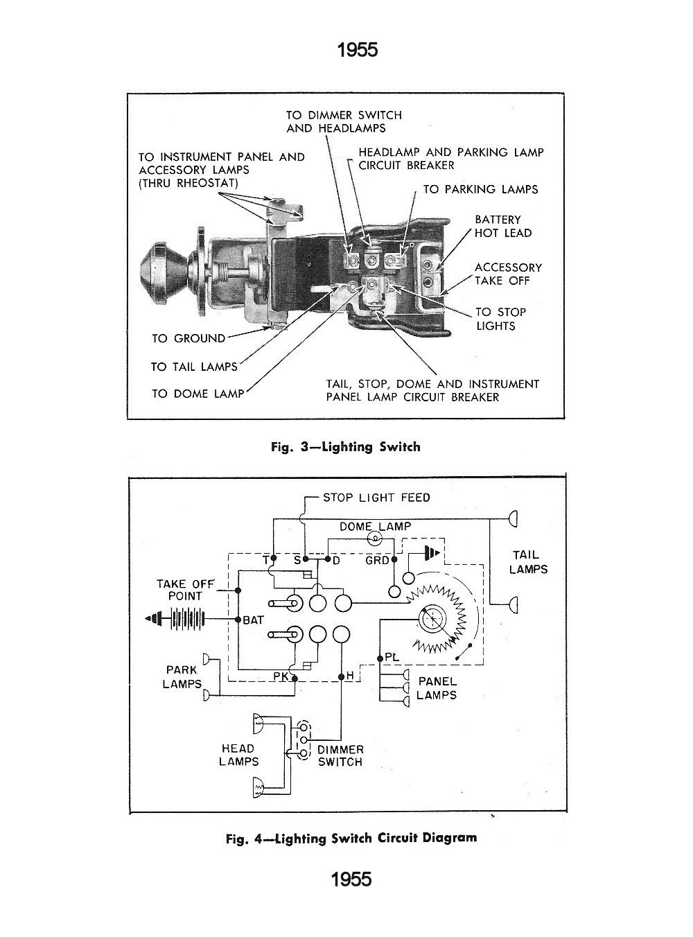
Gm Brake Switch Wiring | Manual E-Books - Gm Headlight Switch Wiring Diagram | Wiring Diagram from 2020cadillac.com Collection of well pump pressure switch wiring diagram. Wiring light switch is first step which learn by a electrician or electrical student. The source power (black wire) is coming in from the left. With alternate light switch wiring, an nm cable supplies line voltage from the electrical panel to a light fixture outlet box. This simple diagram below will give you a better understanding of what this circuit is accomplishing. Want to turn a lamp on with a light switch? Figure 1 below shows the wiring diagram for a basic switch. As we power this circuit, electricity will flow through the hot wire over to the second switch.
The neutral from the source is spliced through to the switch box using the white wire and in this diagram, the white wire is capped with a wire nut.
Want to turn a lamp on with a light switch? It reveals the parts of the circuit as simplified forms, and the power as well as signal connections between the tools. This simple diagram below will give you a better understanding of what this circuit is accomplishing. When the switch is on, the black wire is connected through the switch. The diagram below is based on the video you watched above. Wiring diagram for installing a 1983 12 and newer forward and reverse switch in a 1981 to 1983 club car. Wiring diagram for a switched gfci combo outlet in this diagram, the switch built into the combo device is wired to control the gfci outlet itself. Another nm cable connects from the light fixture box to the switch box. With easy to follow diagrams and instructions, you can have that convenience in no time. Black wire = power or hot wire white wire = neutral bare copper = ground. A wiring diagram is a simplified conventional photographic representation of an electric circuit. Switched 'white' wires are shown in a different wiring diagram. Resources wiring diagram for hpm light switch stove diagrams full version hd quality mediagrame ladolcevalle it how to install a dimmer australia australian honorflightauctions fog toyota other period wire in quora smart digital trends de 3 way jeep cherokee trailer harness total producer xb 5071 double two hunter ceiling fan and control gallery laptrinhx news diy family handyman… read more »
Wiring light switch is first step which learn by a electrician or electrical student. Refer to the smm owner's/installation manual for.variety of generac amp automatic transfer switch wiring diagram. The white neutral wires splice together. 3 way switch wiring diagram part 1 3way switch wiring diagrams #1, #2 and #3 the key to three way switch wiring depends on two main factors. Figure 1 below shows the wiring diagram for a basic switch.
Honeywell Fan Limit Switch Wiring Diagram Gallery from wholefoodsonabudget.com The ground wires splice together and bond to the switch and the box. Single switch wiring diagram 2 fully explained pictures and wiring diagrams about wiring light switches describing the most common switches with photo diagram 2. The white neutral wires splice together. Need help wiring a 3 way switch? Switched 'white' wires are shown in a different wiring diagram. As it goes through the red traveler, it will stop at switch number one. In basic diagram, there are four wires that connect to the motor: For a device controlled by a switch, like a light fixture, the switch breaks the black (hot) wire.
(learn more about how our awesome backlit switches work here) even that one is still pretty straight forward though, here are some diagrams that show the single jumper required on the back of the switch.
With these diagrams below it will take the guess work out of wiring. This simple diagram below will give you a better understanding of what this circuit is accomplishing. In basic diagram, there are four wires that connect to the motor: A single pole light switch wiring diagram. Wiring diagram of forward reverse. The neutral from the source is spliced through to the switch box using the white wire and in this diagram, the white wire is capped with a wire nut. Wiring light switch is first step which learn by a electrician or electrical student. Single switch wiring diagram 2 fully explained pictures and wiring diagrams about wiring light switches describing the most common switches with photo diagram 2. Two black or hot wires, and the earth cable. This might seem intimidating, but it does not have to be. 3 way switch wiring diagram part 1 3way switch wiring diagrams #1, #2 and #3 the key to three way switch wiring depends on two main factors. (learn more about how our awesome backlit switches work here) even that one is still pretty straight forward though, here are some diagrams that show the single jumper required on the back of the switch. The white neutral wires splice together.